Check out my new video, where I talk about my plans to make a new, easier to use, better sounding Pure Data based guitar effect pedal. Make sure to leave a comment and let me know what you think. Feature suggestions are welcome- what would you like to see in this project?
Wednesday, June 8, 2016
Thursday, February 11, 2016
Designing and Building an 8-bit CPU
It's been too long since the last post here! Let's fix that:
The design will be built on two pieces of 9x15 cm .1" perfboard, and connections will be made between chips using enameled magnet wire. I chose this method of construction mainly because it was cheaper that the traditional wire-wrap construction most hobbyists use when attempting this type of digital project- the sockets needed to do wire wrap would cost me about $1.50 a piece, which, times about 50 chips, equals $75. Ok. Maybe that's not so bad, but still- I'm not made of money (read: I'm a cheapskate).
Using ~30 gauge magnet wire, you still are wiring connections point-to-point, but instead of wrapping the wire around posts, you simply turn your soldering iron up to around 700F, and burn the insulation off of the very end of the wire and then solder your connection. The downside to this method is that the burning insulation can release dangerous chemicals, so you need to work in a well-ventilated area. Also, not all magnet wire types are created equal- some have insulation that will not melt under heat
Stay tuned for more updates, pictures and schematics. I'm currently working on the control logic section of the first board, and just finished the clock section. So far, so good!
-Ben, doitnowlabs
Monday, October 27, 2014
Building a Fender 5F2 in Pictures
Disclaimer: Tube amps contain high voltages that can cause injury or death. Do not attempt this project unless you fully understand the risks that come with it, and you have a working knowledge of how tubes work. Thank you, and be safe!
Anyway, on to the article:
Recently I've been working on an all tube guitar amplifier that combines some features of the Fender 5F1, 5F2, and the Fender Twin. It's 5 watts, and uses a 12ax7 in the preamp, a 6V6GT in the power amp, and a 5y3 rectifier tube. I designed the turret board in Autodesk Inventor, and I built it by hand, mostly using parts from Tube Depot. I designed the chassis myself as well (also in Inventor), and while I didn't bend it myself, I did drill all the holes by hand.
It's controls are Volume, Tone, Presence (ala Fender Twin), and a switchable negative feedback circuit, which lets you select between a 22k feedback resistor (More negative feedback, less distortion) and a 57k feedback resistor (Less negative feedback, and more gain). You can definitely hear the difference in tone between these two resistors. It's more pronounced at higher volumes though. This goes for the presence control as well. It seems to do more when the volume is set to 10, because it's a part of the negative feedback circuit. Using a 0.1uf capacitor, it acts like a tone control for the feedback.
The amp's output transformer is from an old 6V6 Hi-Fi amp from the 70s sometime. It's one of two identical ones that I salvaged from the amp. Even though the amp I built is single ended (meaning that it uses only one power tube as opposed to 2 or 4) and the output transformer is for a push pull amp, the sound doesn't seem to be affected. I just used the full primary winding between the 6V6 and B+, and taped off the center tap. This output transformer is rated for 30 watts.
The first time I tried to power up the amp, it seemed to work. There were some unwanted noises and hiss, but it sounded OK for a first try. Then the power transformer blew up... Great! Oh well, it was over 40 years old, so that was to be expected. A few days and a piece of aluminum later, I put in a newer (and much smaller, which is good for weight) power transformer. It has a lower secondary voltage than the last one by about 130vac, but it doesn't seem to matter too much. With this new transformer, the amp sounds great, and has been working for a few weeks now. The B+ voltage off the transformer is 563vac. It has great clean sounds for jazz, and an overdriven sound that reminds me of classic rock from the 60s and 70s.
Here are some pictures that I took while building the amp:
 |
| All the parts before I started building. |
 |
| The top of the chassis. |
 |
| The back of the chassis. From left to right, the holes are for the 5y3, the 6V6, the output jack, and the 12ax7. |
 |
| The output transformer. I got two of these from an old Hi-Fi amp. |
 |
| Front panel controls and home-made turret board installed. |
 |
| The turret board rests on stand-offs so it won't short with the chassis. |
 |
| The copper faceplate was left out of the final amp because the clear finish I put on didn't stick well. |
 |
| The power transformer. A Triode Electronics model. My guess is that it dates back to the 50s. It ended up failing. |
 |
| Wiring up the rectifier tube. |
 |
| Wiring the presence control and the tone control. |
 |
| Wiring the 12ax7 socket. |
 |
| Almost done, all we need now is a new power transformer. Luckily, I had one. |
 |
| The amp, powered up and ready to play. In this picture you can see the replacement power transformer. |
 |
| The rectifier tube. This one is RCA branded, and says it was "made in the U.S.S.R". |
 |
| The 6V6 power tube, |
 |
| and the 12AX7. |
Sunday, August 25, 2013
Optical Tremolo
Time for another write up!
This time for the optical tremolo pedal that I built. What makes this tremolo pedal different from any other, you ask? The answer lies in it's name: Optical tremolo. Yes, that's right, this tremolo uses light to create the volume changing effect that is a tremolo. This is how it does that:
And LED light is positioned above a photo resistor, and a motor spins a disk with a pattern cut out of it . When the disk spins, light can shine through the patter cut out of it, thus hitting the photo resistor.
When light hits a photo resistor, it's resistance increases. So when you run a signal through the photo resistor while you have the LED lit and the motor with a pattern disk spinning, you get a pattern of varied resistance (and therefor volume) that corresponds to the pattern on the disk. Voilà! Tremolo.
I got the idea for this project from MAKE: Magazine Vol. 15, but you can read the article online for free here: MAKE: Optical Tremolo
Everything is powered off of a 9 volt battery.
The only controls on the tremolo pedal are a switch to reverse the motor (For A-symmetrical pattern disks), a 5-way switch speed control, an "amount" potentiometer (wired in series with the photo resistor), and an on/off switch. Watch a video demo on my Youtube channel!
Finally, here are some pictures:
(Pattern disks aren't pictured, because I seem to have lost them... Haha)


The Raspberry Pi Guitar Effect Box
Today I wanted to post an article about my Raspberry Pi based guitar effect box. Here we go:
This project, as mentioned previous, is a guitar effect unit based on and powered by a Raspberry Pi "micro-computer" and the free DSP software "Pure Data". All of the effects are written in the Pure Data (Or "PD") language. The effect box currently contains 15 effects in all, but the entire system was built around the concept that the user should be able to switch out effects for new ones very easily. Continuing on, the effect unit (Or "pedal" as I'll refer to it from now on) consists of six main components: The buttons, the potentiometers, the VFD display, the ADC (Reads pots), the USB sound card, and the Raspberry Pi itself. I'll now go over what each component does. First, the buttons. There are three momentary push buttons on the front panel of the pedal. They enable you to cycle through effects and enter menu screens. The top most button acts as a "next" button, cycling through to the next effect, and the bottom most buttons acts as a "previous" button, cycling through to the previous effect. When the middle button is pressed, the pedal enters "edit mode", in which the user can edit the parameters of an effect, such as a chorus's speed or depth, by using the four potentiometers on the front of the pedal. This brings us into a description of how the potentiometers function. Each potentiometer is wired as a voltage divider into a channel of the ADC chip, which converts the voltage off the pot to a digital value, and that digital value takes the place of a hard coded value in a PD effect file, thus changing a certain parameter of an effect. Moving on, when the pedal is in "normal" (non-edit-mode) the VFD display shows the name of the currently selected effect, and what it's editable parameters are. The parameters are listed from right to left, corresponding to their own potentiometer. Using the image below as an example, the user has selected the effect called "Chorus" using the next/previous buttons. You can see that the editable parameters for this effect are (from right to left): Speed, Depth, and Fdbk (Feedback). If the pedal were in edit mode, the parameter "Speed" would be controlled by potentiometer #1, the one closest to the orange cable; the other parameters following suit with potentiometers #2, and #3.
Now we have covered 4 of the six components. Next is the USB sound card.
This project, as mentioned previous, is a guitar effect unit based on and powered by a Raspberry Pi "micro-computer" and the free DSP software "Pure Data". All of the effects are written in the Pure Data (Or "PD") language. The effect box currently contains 15 effects in all, but the entire system was built around the concept that the user should be able to switch out effects for new ones very easily. Continuing on, the effect unit (Or "pedal" as I'll refer to it from now on) consists of six main components: The buttons, the potentiometers, the VFD display, the ADC (Reads pots), the USB sound card, and the Raspberry Pi itself. I'll now go over what each component does. First, the buttons. There are three momentary push buttons on the front panel of the pedal. They enable you to cycle through effects and enter menu screens. The top most button acts as a "next" button, cycling through to the next effect, and the bottom most buttons acts as a "previous" button, cycling through to the previous effect. When the middle button is pressed, the pedal enters "edit mode", in which the user can edit the parameters of an effect, such as a chorus's speed or depth, by using the four potentiometers on the front of the pedal. This brings us into a description of how the potentiometers function. Each potentiometer is wired as a voltage divider into a channel of the ADC chip, which converts the voltage off the pot to a digital value, and that digital value takes the place of a hard coded value in a PD effect file, thus changing a certain parameter of an effect. Moving on, when the pedal is in "normal" (non-edit-mode) the VFD display shows the name of the currently selected effect, and what it's editable parameters are. The parameters are listed from right to left, corresponding to their own potentiometer. Using the image below as an example, the user has selected the effect called "Chorus" using the next/previous buttons. You can see that the editable parameters for this effect are (from right to left): Speed, Depth, and Fdbk (Feedback). If the pedal were in edit mode, the parameter "Speed" would be controlled by potentiometer #1, the one closest to the orange cable; the other parameters following suit with potentiometers #2, and #3.
 | |||||
| The front panel, showing the buttons, pots, and VFD |
 |
| Inside the pedal |
The photo above shows the internals of the pedal. In the top center you can see the Raspberry Pi model B, the heart of the device. Connected to it via the GPIO pins is the main circuit board, which holds the ADC chip and various resistors. I'll provide a link to the schematic at the end of this post. Also connected to the Raspberry Pi is a small black rectangle with both a yellow and a black cable connected to it. This is the USB sound card. The yellow cable is the audio input from your guitar, and the black is processed audio out from Pure Data. The reason a USB sound card was necessary was because the Pi doesn't have a built in audio-in port. Having covered 5 of the 6 main components, all that remains is the Raspberry Pi. I'm not the person to explain the Pi, so I'll redirect you here to learn more about it.
Finally, to end this post, here are some more pictures:
 |
| The VFD display and four pots |
 |
| A shot of the pedal with my amp and strat |
Monday, March 4, 2013
The 'Tiger Eye' Robot Writeup - As seen on raspberrypi.org
Hi! My name’s Ben.
I’ve always had a big interest in robotics and electronics in general, so when I heard about the Raspberry Pi, I knew I had to build a robot around it. This is what I came up with:
 The base of the robot is an old iRobot roomba 4000 with all of the cleaning brushes and their respective motors removed.
The model of roomba that I used has two drive wheels and a coaster wheel in front, and the drive wheels draw almost 300mA of current, so powering them directly off of the Raspberry Pi’s GPIO obviously wouldn’t work. So, I considered using a relay board to control the two drive motors from the GPIO. However, it turns that all the good boards were a little too expensive for a hobby project, so I decided to open the roomba up and see if I could somehow control the motors from the existing circuitry. Guess what? It turns out that there are four small transistors on the main board that power four larger transistors that deliver power to the motors. This means that there are two transistors per motor: one for forwards and one for backwards.
 They’re labeled Q13, Q14, Q30 and an un-labeled one near R129.
I had a little help in discovering this from a video that a man named Dean Segovis had posted on YouTube, but I ended up taking a multimeter to the board; just to make sure that I wasn’t hooking my precious pi up to anything dangerous. You can watch Dean’s video here: https://www.youtube.com/watch?v=TVp6QWcoilk.
Once I had confirmed the location of the transistors I needed on the board, I connected their bases to GPIO pins 4, 17, 18 and 21 on the Raspberry pi with with a 16 pin socket that I had lying around.
To power the Raspberry Pi, I soldered together a power supply circuit around a 1 amp 5 volt regulator (basically the regulator and two capacitors) on a piece of perf board and had the 5v output from the regulator run to a micro USB connector. I also added some miscellaneous components to the circuit, like a power switch, a 2.5 Amp fuse, a 12 volt in socket and some 12 volt out sockets; one of which the camera is plugged into. The roomba’s main board is also plugged into a 12 volt out socket.
For the camera, I just used an ip network camera from the company Vivotek.
I had tried to use a USB webcam that you might use for skype calls, but streaming video from the pi slowed it way down and the picture quality wasn’t as good as I had wanted. I wasn’t using the best webcam in the world, though.
To hold the Pi in place on the robot, I just glued some plastic pegs where I wanted it to go:
One in between the USB and Ethernet ports, one in between the audio jack and the component video port, one near the HDMI port
and one near the SD card slot. This makes it easy to remove the Pi from the robot when It isn’t in use, yet it holds it in place very well.
 The entire robot is powered off of a small 12 volt lead acid battery
that fits nicely into the slot where the roomba’s original battery went.
I could have used the original battery, but the one that came with my
roomba was extremely old and wouldn’t take a charge any more. .
The entire robot is powered off of a small 12 volt lead acid battery
that fits nicely into the slot where the roomba’s original battery went.
I could have used the original battery, but the one that came with my
roomba was extremely old and wouldn’t take a charge any more. .
Lastly, I wrote some software in python to take input from a Nintendo wii remote and transmit the input it got to the Pi over wifi, where it’s decoded by another piece of python software and the wheels are moved according to the position of the joysticks on the wii remote. You can get my code at the links below:
Server.py – This one runs on the Raspberry Pi:
Server.py
Client.py – This one runs on your “base station” computer, a laptop for example:
Client.py
You can watch a short video of me driving the robot around on my YouTube channel:
https://www.youtube.com/user/doitnowlabs
And I think that’s about it. If I was unclear about anything or if you want a more detailed description of my project, please email me at benhjake (at) gmail.com , or leave a comment below. Also, if you replicate my project, I’d love to see a picture or two. You could email those to the same address. Thanks, and Happy Hacking!
I’ve always had a big interest in robotics and electronics in general, so when I heard about the Raspberry Pi, I knew I had to build a robot around it. This is what I came up with:
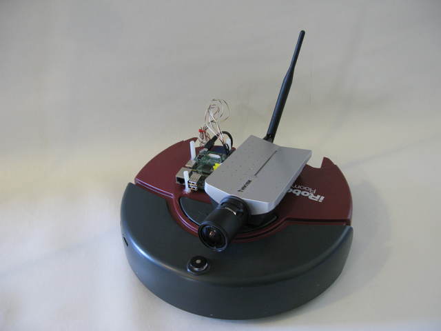
The robot, ready to do your bidding. Necessary wifi dongle not shown.
The model of roomba that I used has two drive wheels and a coaster wheel in front, and the drive wheels draw almost 300mA of current, so powering them directly off of the Raspberry Pi’s GPIO obviously wouldn’t work. So, I considered using a relay board to control the two drive motors from the GPIO. However, it turns that all the good boards were a little too expensive for a hobby project, so I decided to open the roomba up and see if I could somehow control the motors from the existing circuitry. Guess what? It turns out that there are four small transistors on the main board that power four larger transistors that deliver power to the motors. This means that there are two transistors per motor: one for forwards and one for backwards.

The four small transistors I mentioned are circled in red. Behold my soldering!
I had a little help in discovering this from a video that a man named Dean Segovis had posted on YouTube, but I ended up taking a multimeter to the board; just to make sure that I wasn’t hooking my precious pi up to anything dangerous. You can watch Dean’s video here: https://www.youtube.com/watch?v=TVp6QWcoilk.
Once I had confirmed the location of the transistors I needed on the board, I connected their bases to GPIO pins 4, 17, 18 and 21 on the Raspberry pi with with a 16 pin socket that I had lying around.
To power the Raspberry Pi, I soldered together a power supply circuit around a 1 amp 5 volt regulator (basically the regulator and two capacitors) on a piece of perf board and had the 5v output from the regulator run to a micro USB connector. I also added some miscellaneous components to the circuit, like a power switch, a 2.5 Amp fuse, a 12 volt in socket and some 12 volt out sockets; one of which the camera is plugged into. The roomba’s main board is also plugged into a 12 volt out socket.
For the camera, I just used an ip network camera from the company Vivotek.
I had tried to use a USB webcam that you might use for skype calls, but streaming video from the pi slowed it way down and the picture quality wasn’t as good as I had wanted. I wasn’t using the best webcam in the world, though.
To hold the Pi in place on the robot, I just glued some plastic pegs where I wanted it to go:
One in between the USB and Ethernet ports, one in between the audio jack and the component video port, one near the HDMI port
and one near the SD card slot. This makes it easy to remove the Pi from the robot when It isn’t in use, yet it holds it in place very well.

The ‘holder’, with Rpi inserted.
Lastly, I wrote some software in python to take input from a Nintendo wii remote and transmit the input it got to the Pi over wifi, where it’s decoded by another piece of python software and the wheels are moved according to the position of the joysticks on the wii remote. You can get my code at the links below:
Server.py – This one runs on the Raspberry Pi:
Server.py
Client.py – This one runs on your “base station” computer, a laptop for example:
Client.py
You can watch a short video of me driving the robot around on my YouTube channel:
https://www.youtube.com/user/doitnowlabs
And I think that’s about it. If I was unclear about anything or if you want a more detailed description of my project, please email me at benhjake (at) gmail.com , or leave a comment below. Also, if you replicate my project, I’d love to see a picture or two. You could email those to the same address. Thanks, and Happy Hacking!
Subscribe to:
Posts (Atom)